Data for Q. 1 and Q. 2: Consider a 6.4 kV, three phase overhead feeder having impedance f 0.4 + j0.8 Ω/km. The average power factor of the load connected to the feeder is 0.85.
1. The Kdrop factor of the feeder is
- 0.01073 % drop / kVA-km
- 0.00185 % drop / kVA-km
- 0.00107 % drop / kVA-km
- 0.01855 % drop / kVA-km
2. The Krise factor of the feeder is
- 0. 00112 % rise / kVAr-km
- 0.01954 % rise / kVAr-km
- 0.00195 % rise / kVAr-km
- 0.01128 % rise / kVAr-km
Data for Q. 3, Q. 4 and Q. 5: In a distribution feeder shown in the following figure, the loads are S1 = 400 kVA, S2 = 500 kVA and S3 = 600 kVA.
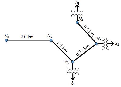
3. If the Kdrop factor of the feeder is 0.000147 %drop / kVA-km, the total percent drop from N0 to N3 is.
- 0.89 %
- 0.30 %
- 0.93 %
- 0.63 %
4. If the total percentage drop from N0 to N4 is 2.5%, then the Kdrop factor of the feeder is
- 0.001960 % drop / kVA-km
- 0.003922 % drop / kVA-km
- 0.000196 % drop / kVA-km
- 0.000392 % drop / kVA-km
5. A capacitor of 200 kVAr is connected at the node N4. If the voltage drop is improved from 2.5 % to 2 % due to capacitor for the given loading, then the Krise factor (% rise / kVAr-km) of the feeder is
- 0.005263 % rise / kVAr-km
- 0.000526 % rise / kVAr-km
- 0.002630 % rise / kVAr-km
- 0.000263 % rise / kVAr-km
Data for Q. 6 and Q. 7: A distribution feeder is shown in the following figure. The substation is at node N0.
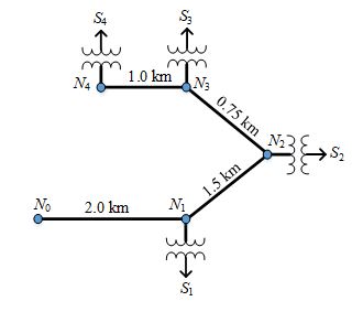
6. The loads S1, S2, S3 and S4 are in proportion of 1:3:2:2 and the Kdrop factor is 0.000254 % drop / kVA-km. If the percentage voltage drop from N0 to N4 is 3%, then the total load of the feeder at the substation is.
- 3000 kVA
- 1500 kVA
- 3750 kVA
- 2250 kVA
7. To limit the voltage drop up to 2.5%, a capacitor is connected at the terminal N4. If the Krise factor is 0.0004 % rise / kVAr-km, the kVAr rating of the capacitor is
- 312.5 kVAr
- 263.2 kVAr
- 238.1 kVAr
- 357.1 kVAr
8. As shown in the following figure, a uniformly distributed load is lumped at two locations such that the calculated drop and power loss are correct. If length of the line is l then the value of d1 and d2, respectively are
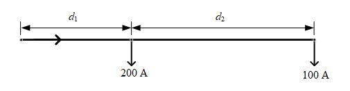
- 0.25l and 0.75l
- 0.33l and 0.67l
- 0.5l and 0.5l
- 0.75l and 0.25l
9. A three phase, 12.47 kV feeder is supplying a distribution area of rectangular in shape. The length (l) and width (w) of the rectangular area is 5 km and 3 km respectively. The impedance of the feeder is 0.4 + j0.8 Ω/km. If the load desnsity of the area is 1500 kVA/km2 at unity pf, then the total voltage drop at the end of the feeder will be.
- 2083.462 V
- 3608.660 V
- 1804.330 V
- 1041.731 V
10. A three phase, 11 kV feeder with impedance of 0.31 + j0.75 is supplying a uniformly distributed load of 6000 kVA at 0.9 lagging pf. If the voltage drop at the end of the feeder is 110 V, the total power loss in the feeder will be.
- 61.40 kW
- 28.71 kW
- 6.735 kW
- 35.45 kW